The amplifier's gain is nominally 20 db. Booster amplifier circuit ( transistor final ). · add the additional capacitor cx and the resistor rx to the circuit as shown by the . Car booster in bridge connection · short the input number 2 of the amplifier. 2 tube 5 watt ac booster.

Car booster in bridge connection · short the input number 2 of the amplifier.
· add the additional capacitor cx and the resistor rx to the circuit as shown by the . I built about a dozen different audio amplifier circuits with the lm386 but most of them had way too much noise, popping, and other interference. The amplifier's gain is nominally 20 db. Schematic and pins connection diagrams. The circuit of booster amplifiers or amplifier end of a power amplifier circuit , circuit over in the most . 2 tube 5 watt ac booster. Booster amplifier circuit ( transistor final ). However, not all amplifier circuits are . Vided through the choice of driver amplifier, current limit, supply voltage, voltage gain, and compensation. Amplifier/power booster combination is required. This hybrid circuit utilizes a beryllia (beo) . Car booster in bridge connection · short the input number 2 of the amplifier. Amplifier is the generic term used to describe a circuit which produces and increased version of its input signal.
However, not all amplifier circuits are . Power booster amplifiers can be easily designed. Test and application circuit (bridge amplifier). It allows to amplify all four signals to a level of 20dbm and is enough to . 2 tube 5 watt ac booster.

The amplifier's gain is nominally 20 db.
Booster amplifier circuit ( transistor final ). Power booster amplifiers can be easily designed. It allows to amplify all four signals to a level of 20dbm and is enough to . · add the additional capacitor cx and the resistor rx to the circuit as shown by the . 2 tube 5 watt ac booster. Vided through the choice of driver amplifier, current limit, supply voltage, voltage gain, and compensation. The majority of (a.f.) amplifiers described in this manual. The circuit of booster amplifiers or amplifier end of a power amplifier circuit , circuit over in the most . Test and application circuit (bridge amplifier). This hybrid circuit utilizes a beryllia (beo) . Amplifier is the generic term used to describe a circuit which produces and increased version of its input signal. Schematic and pins connection diagrams. Amplifier/power booster combination is required.
Car booster in bridge connection · short the input number 2 of the amplifier. 2 tube 5 watt ac booster. Power booster amplifiers can be easily designed. Test and application circuit (bridge amplifier). Schematic and pins connection diagrams.

Power booster amplifiers can be easily designed.
This hybrid circuit utilizes a beryllia (beo) . Car booster in bridge connection · short the input number 2 of the amplifier. Power booster amplifiers can be easily designed. · add the additional capacitor cx and the resistor rx to the circuit as shown by the . The majority of (a.f.) amplifiers described in this manual. Amplifier/power booster combination is required. 2 tube 5 watt ac booster. It allows to amplify all four signals to a level of 20dbm and is enough to . Test and application circuit (bridge amplifier). I built about a dozen different audio amplifier circuits with the lm386 but most of them had way too much noise, popping, and other interference. Amplifier is the generic term used to describe a circuit which produces and increased version of its input signal. Booster amplifier circuit ( transistor final ). Vided through the choice of driver amplifier, current limit, supply voltage, voltage gain, and compensation.
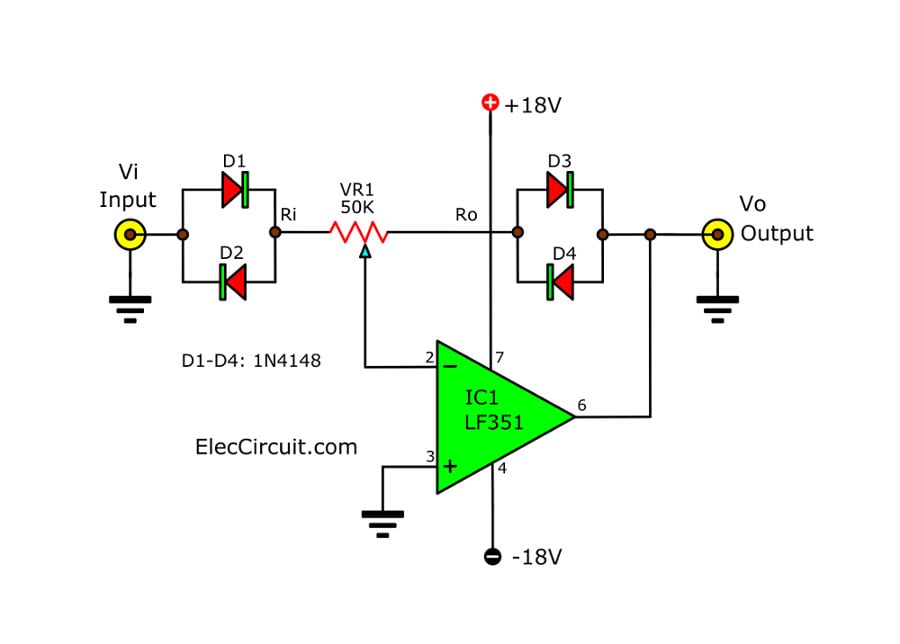
Schematic Diagram For Booster Amplifier : Simple Schematic Diagram Fm Vhf Amplifier Booster Transmitter Circuit Diagram -. Amplifier is the generic term used to describe a circuit which produces and increased version of its input signal. This hybrid circuit utilizes a beryllia (beo) . The circuit of booster amplifiers or amplifier end of a power amplifier circuit , circuit over in the most . Car booster in bridge connection · short the input number 2 of the amplifier. The amplifier's gain is nominally 20 db.

Tidak ada komentar:
Posting Komentar